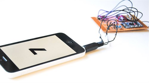
It worked. Excellent, Now that we could pass signals through to our devices we could make certain signals mean certain things, such as a 1 and a 0. I don't know Objective-C and, until recently, if you wanted to write an app that needed access to hardware (the audio jack) you'd probably have to write in Obj-C. That said, guess what? I know C++ (well, a good bit of it at least), and guess what you can write iOS apps with if you really want to? C++ – well, Objective-C++. openFrameworks is a fantastic framework that was designed to help code creative applications without having to know every aspect of programming inside-out. I'd used it before and openFrameworks has access to iPhone audio so it seemed perfect to use.
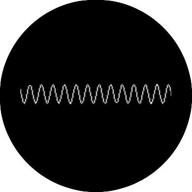
The first thing I wrote was a quick app to display the waveforms being sent by the Arduino just so I could see that I was in fact able to receive audio. Next, I ran it through an FFT (Fast Fourier Transform) algorithm and wrote a quick app to output the data in a graph. This made it easier to visually identify frequencies that were as different as possible from each other, thus reducing the chance that the signal could be misread.
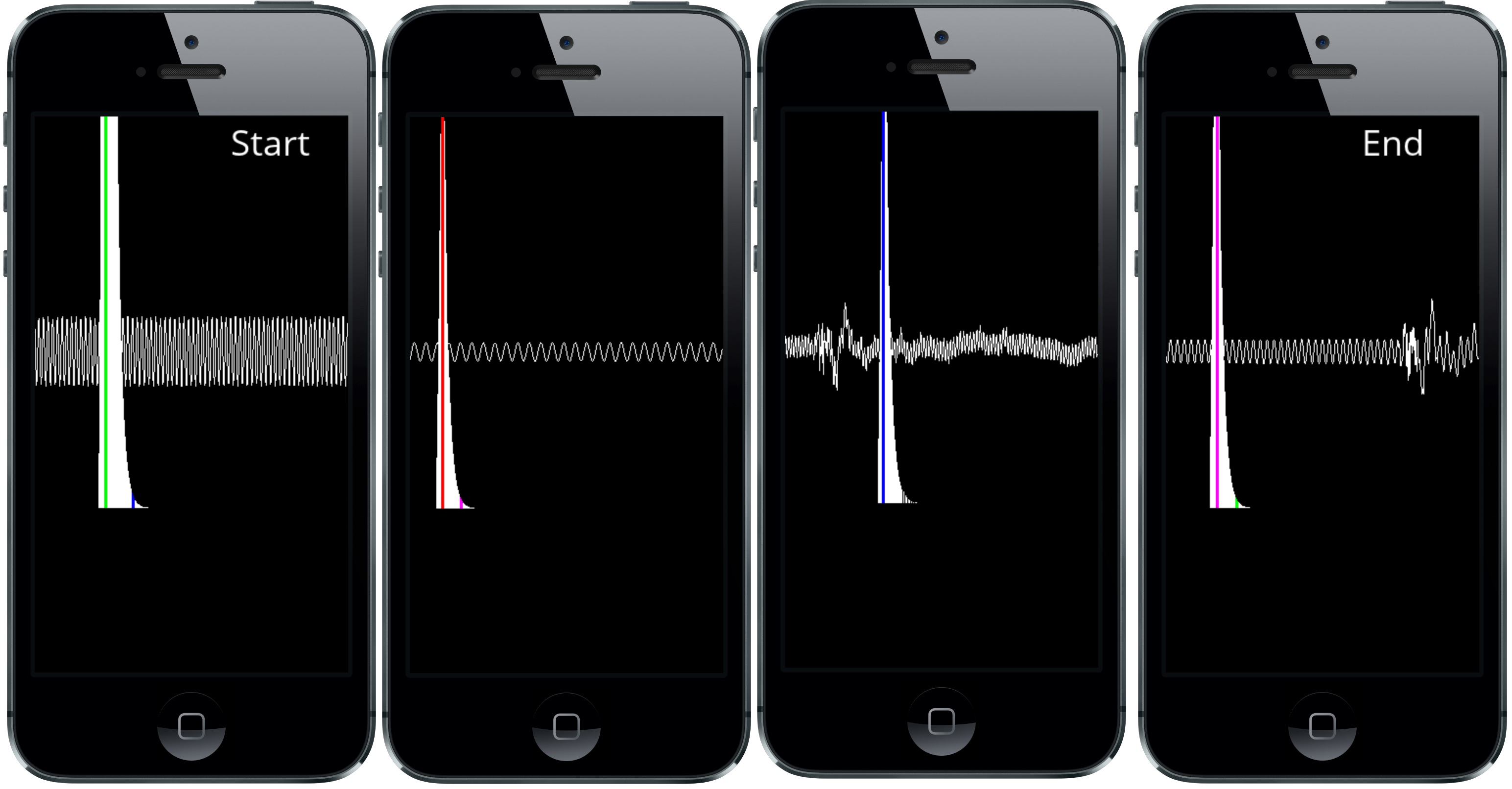
After some manual tweaking of various frequencies, I decided that 80, 120, 50 and 300 Hz were perfect for signalling data to the phone. Why four frequencies instead of two? When transferring data in this way, we need to be conscious of the time as well as what's being sent – if we have no measure of how long each bit is signalled for, then we have no way of knowing when there are two of the same bits sent in sequence after each other. When we first tried to sync up our devices, our iPhone would play a sound through the jack which our Arduino would recognise and after that tone had finished, the Arduino would send the 1s and 0s to our phone. Though simple in principle, this quickly became tricky in practice; with wire crossovers, poor internal time-keeping and the iPhone's general unwillingness to play the tone exactly when we wanted it to, the reliability of our system was maybe 50% (that's off the top of my head, I didn't keep records of how many times it failed/succeeded).
Ultimately, I realised that we could probably get far more reliable results between our devices if, instead of waiting for a timing signal, we sandwiched our data in-between two extra frequencies – one that signalled that the data was about to start and another that signalled it had ended. This does mean that the Arduino operates entirely without influence from our iPhone, but the trade-off is a better ability to parse and process data on the phone side.
Once I had an app that could receive the data (though at this point it could not interpret that data) I set about writing the code for the Arduino to send that data. Our UV sensor generated a value that indicated the amount of watts per square centimetre the sun was outputting. That's all well and good, but it doesn't help us greatly. The UV index is actually a little tricky to calculate; it accounts for both UVA and UVB rays, both of which are damaging to skin but have different wavelengths and, given a number of environmental variables, can differ in their intensities from one another. Our sensor can detect both UVA and UVB rays but it cannot differentiate one from another, so we couldn't do the weighting normally applied to the sum that calculates W/m2 – but we could still do the calculation which would give us a value that closely correlates with the UV Index observed. Once we had that we needed to convert that number into a binary string consisting of 8 bits so that we could send it through the audio jack. A simple function call converted our number into a binary string and then we took each 1 and 0 and added them to an array that we would work through when generating the tones.
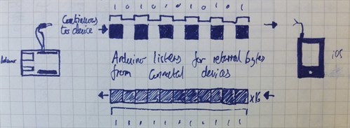
Now to the transmission part. This was simple enough, we had our array of 8 bits making up our binary number, and all we needed to do was iterate through those values and check if it was a 1 or a 0. Depending on which number we had, we'd generate the appropriate tone. This required a little bit of thinking... a tone is made by the length of time between the peak and the trough of the sound wave. To generate a tone of, say, 300Hz, we'd make a high for 300 microseconds and then a low for 300 microseconds and the same for every other tone – all we'd do is adjust the time that the tone had a high and a low for. Simple enough, but this did leave us with a problem... it takes longer to generate a 300Hz tone (600 microseconds) than it does for an 80Hz tone (160 microseconds), so in the time that it takes to generate a single oscillation of a 300Hz tone we could generate four oscillations of the 80Hz tone. Fortunately, this was easily remedied by making each tone last for a pre-set amount of time to signify a single bit. I decided on 50ms to be the time that it would take to transmit each bit – this gave us a data transfer rate of roughly two bytes per second which is super slow, but seeing as we only needed a single byte of data irregularly, it suited our need perfectly. In applications where speed in the transfer is a necessity, the developers have typically been inclined to use frequencies below 50Hz that vary by no greater than 10Hz per value – the Chirp protocol is a great example of this and if you get time to read up on its implementation, I'd highly recommend it.
Now we're transmitting useful data there's just the matter of putting it back together. I already had an app that could make sense of the different tones, all that needed doing was the timing handlers and dealing with the start and end tones. The rules for checking and parsing the data were pretty simple:
- If we were reading data but hadn't heard a start tone, we disregarded that data – we'd started the read too late.
- If we were reading data and we had heard the start tone, we'd check the frequency of the tone every 50 microseconds and store in an array.
- If we heard the end tone and had 8 bits stored, we parsed the data and reset the values for the next read. If there were fewer than 8 bits stored, we'd disregard; we'd had a bad read.
If we did in fact have 8 bits, all that was left to do was some bit-shifting to convert the binary values back into a human readable value. If the number was less than 12, then we could be fairly confident we'd had an accurate reading and a good data transfer; if it was more than 12, either we'd had a bad read... or some kind of supernova had gone off... either way, the value was useless to us and so it was disregarded.
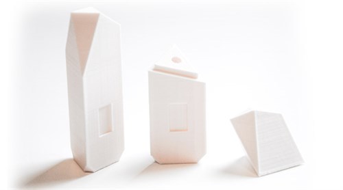
At this point, we had reliable data transmission from our Arduino + sensor to our iPhone. All that remained now was to attach the circuit to our phones. We would have loved to have made it tiny enough to fit on a keychain like in our
concepts but this is a prototype, not a finished product, so we had to build the circuit ourselves. We settled for containing the sensor in an iPhone case that attached to the back of the device – it's not the smallest accessory in the world, but it demonstrates the portability of such devices.
To round off, when we set out to make our UV scanner, we were thinking about the potential good it could do in helping people remain aware of the dangers of exposure to the sun. The implementation of this idea set us down the road of learning about different methods of transferring data and it has left me with nothing but respect for the guys that put together the original networking standards. In a world where we can transmit gigabytes of data in minutes, sitting down and constructing your own (reliable) data transmission protocol is a toughie and we've learned a lot from it. Hopefully, with the release of our code and this blog, it'll be a little easier for people to get stuck into making their own peripherals if they are so inclined.
